Home

Látszólag készít optimális chopper transformer inverter circuit diagram döntsd el Felülvizsgálat Rab

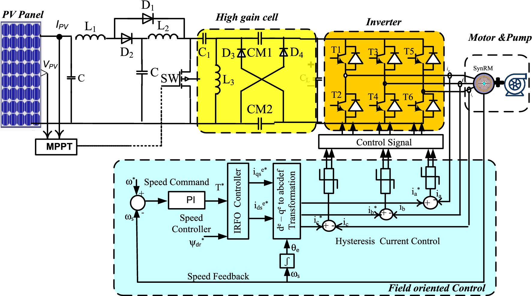
High gain chopper supplied from PV system to fed synchronous reluctance  motor drive for pumping water application | Scientific Reports
High gain chopper supplied from PV system to fed synchronous reluctance motor drive for pumping water application | Scientific Reports

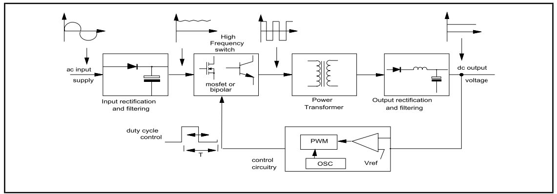
Many circuits: HOW TO MAKE SMPS FERRITE TRANSFORMER (CHOPPER)

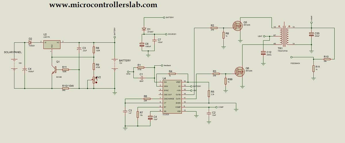
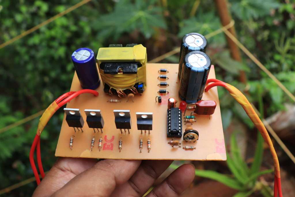
Solar inverter using sg3525

Circuit Diagram of SPRS Employing Line Commutated Inverter with... |  Download Scientific Diagram
Circuit Diagram of SPRS Employing Line Commutated Inverter with... | Download Scientific Diagram

1000 watt power inverter circuit diagram | CircuitsTune

500 watts inverter circuit -12 volt to 220 volt - Soldering Mind

Tahmid's blog: Using the SG3525 PWM Controller - Explanation and Example: Circuit  Diagram / Schematic of Push-Pull Converter
Tahmid's blog: Using the SG3525 PWM Controller - Explanation and Example: Circuit Diagram / Schematic of Push-Pull Converter
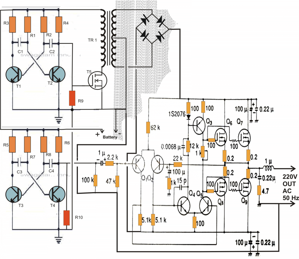
5kva Ferrite Core Inverter Circuit - Full Working Diagram with Calculation  Details | Homemade Circuit Projects
5kva Ferrite Core Inverter Circuit - Full Working Diagram with Calculation Details | Homemade Circuit Projects
What is Chopper Circuit? Need and Operating Principle of Chopper Circuits -  Electronics Coach
What is Chopper Circuit? Need and Operating Principle of Chopper Circuits - Electronics Coach

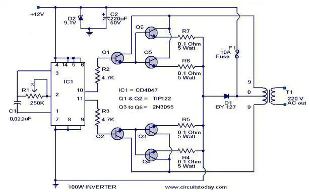
100 Watt Inverter-Circuit Diagram, Parts List & design Tips

i need someone to Design the circuit diagram of ups | Chegg.com

Pin on Circuit
Pin on Circuit

Pin on skillful
Pin on skillful

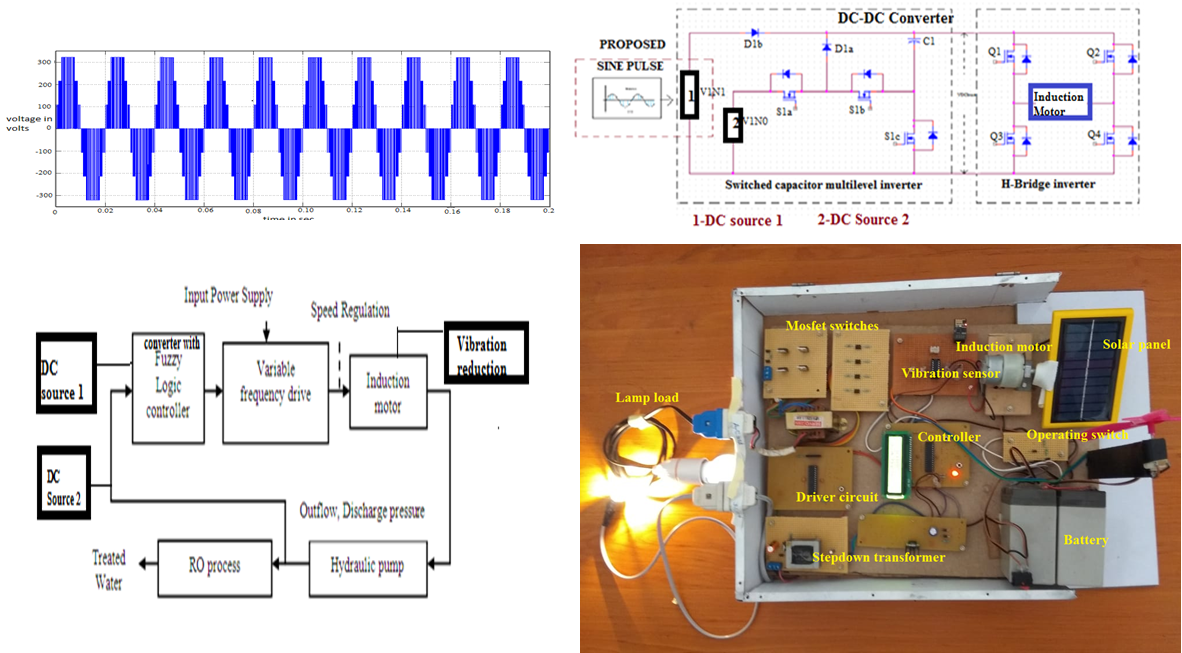
Analysis and design of a novel hybrid topology for power quality  improvement using multilevel inverter fed induction motor by reducing  vibration for textile wastewater treatment applications | Extrica -  Publisher of International
Analysis and design of a novel hybrid topology for power quality improvement using multilevel inverter fed induction motor by reducing vibration for textile wastewater treatment applications | Extrica - Publisher of International

Designing Isolated Flyback Converter Circuits: Transformer Design  (Calculating numerical values) | Overview of Design Method of PWM AC-DC  Flyback Converters | TechWeb
Designing Isolated Flyback Converter Circuits: Transformer Design (Calculating numerical values) | Overview of Design Method of PWM AC-DC Flyback Converters | TechWeb

Operating stages of the chopper circuit when the input voltage is 220 V. |  Download Scientific Diagram
Operating stages of the chopper circuit when the input voltage is 220 V. | Download Scientific Diagram

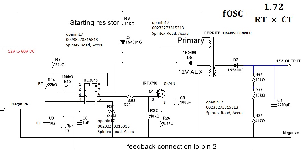
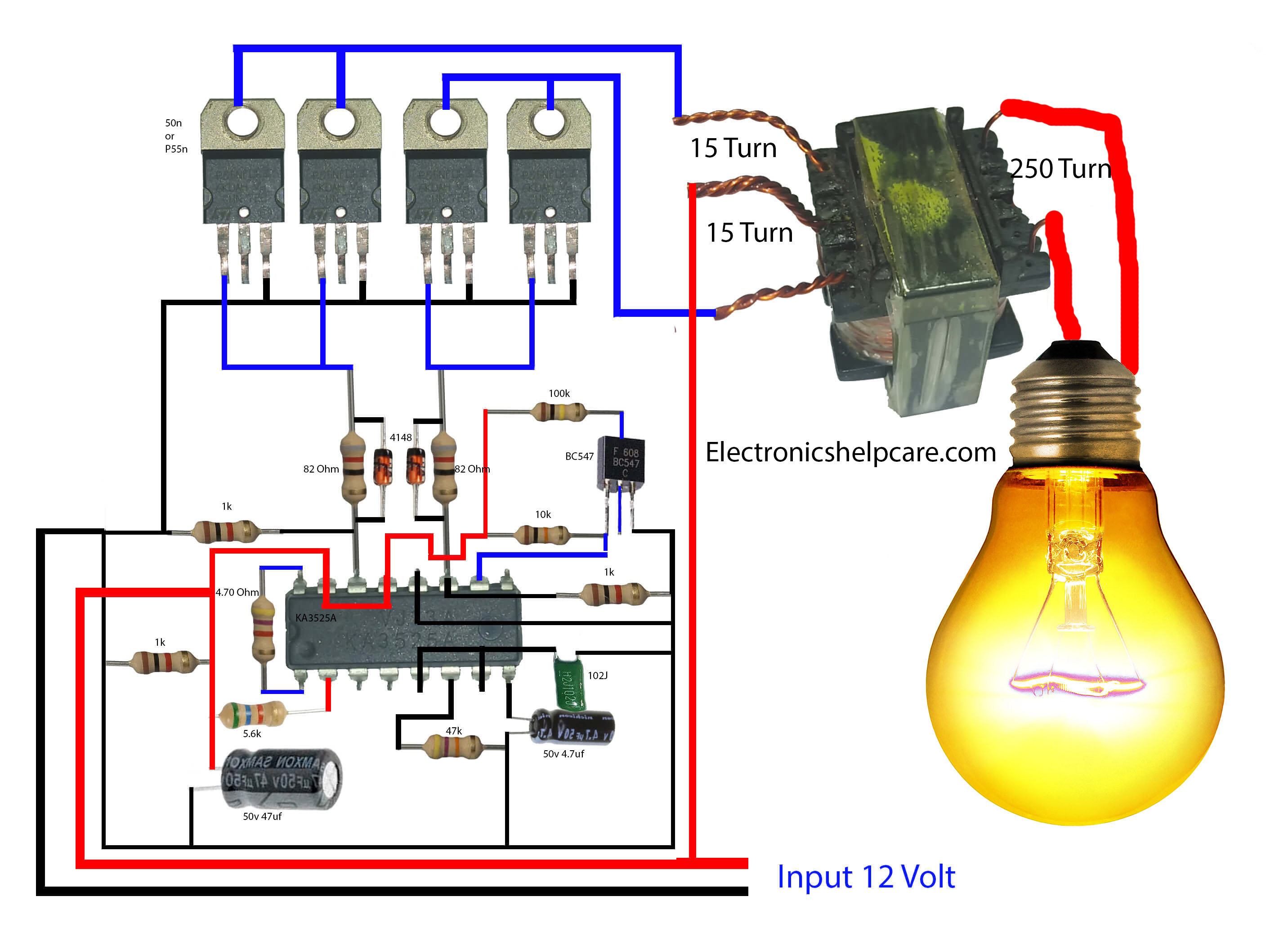
how to make an inverter using 12volts - Electronics Help Care

inverter circuit Page 2 : Power Supply Circuits :: Next.gr

12 Steps for Designing SMPS Transformers : The Talema Group

Transformerless H-Bridge Inverter Circuit

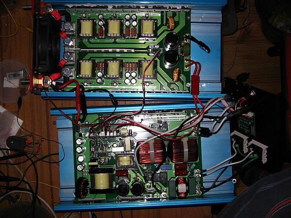
The Power Jack 3500 Watt inverter - buyers beware!

how to build a 2KVA inverter circuit diagram under Repository-circuits  -26819- : Next.gr
how to build a 2KVA inverter circuit diagram under Repository-circuits -26819- : Next.gr

DC Chopper Circuit Using Thyristors-SCRs - Electronic Projects, Power  Supply Circuits, Circuit Diagram symbols, Audio Amplifier Circuit pdf &  Engineering Projects
DC Chopper Circuit Using Thyristors-SCRs - Electronic Projects, Power Supply Circuits, Circuit Diagram symbols, Audio Amplifier Circuit pdf & Engineering Projects

Buck-Boost Converter: What is it? (Formula and Circuit Diagram) |  Electrical4U
Buck-Boost Converter: What is it? (Formula and Circuit Diagram) | Electrical4U